Moving the homelab into the rack
Over the past few weeks, I’ve been receiving the various parts that I ordered for my DIY 10-inch rack. As I mentioned in my last post, I was planning on moving my homelab into a rack, and I’ve finally gotten around to doing it.
All of the CAD files for the rack can be viewed on Onshape. Feel free to make a copy and modify it to suit your needs.
The Rack
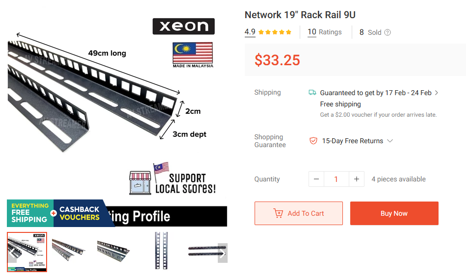
The rack itself is made from two pairs of 9U server rails that I got from Shopee. They look like they are meant to be drilled into wooden furniture, but a rail is a rail. Since they are individual rails, I can position them however I want, which in my case is as a 10-inch rack.
Even though the rails are listed as 9U, they are actually 11U long. The extra 2U is there to let you mount them however you like. I was originally planning on printing some platforms with holes to slot the rails through, but my 3d printer is only 255mm wide, which is fine for the 10-inch width, but not enough when you add in the width of the rails.
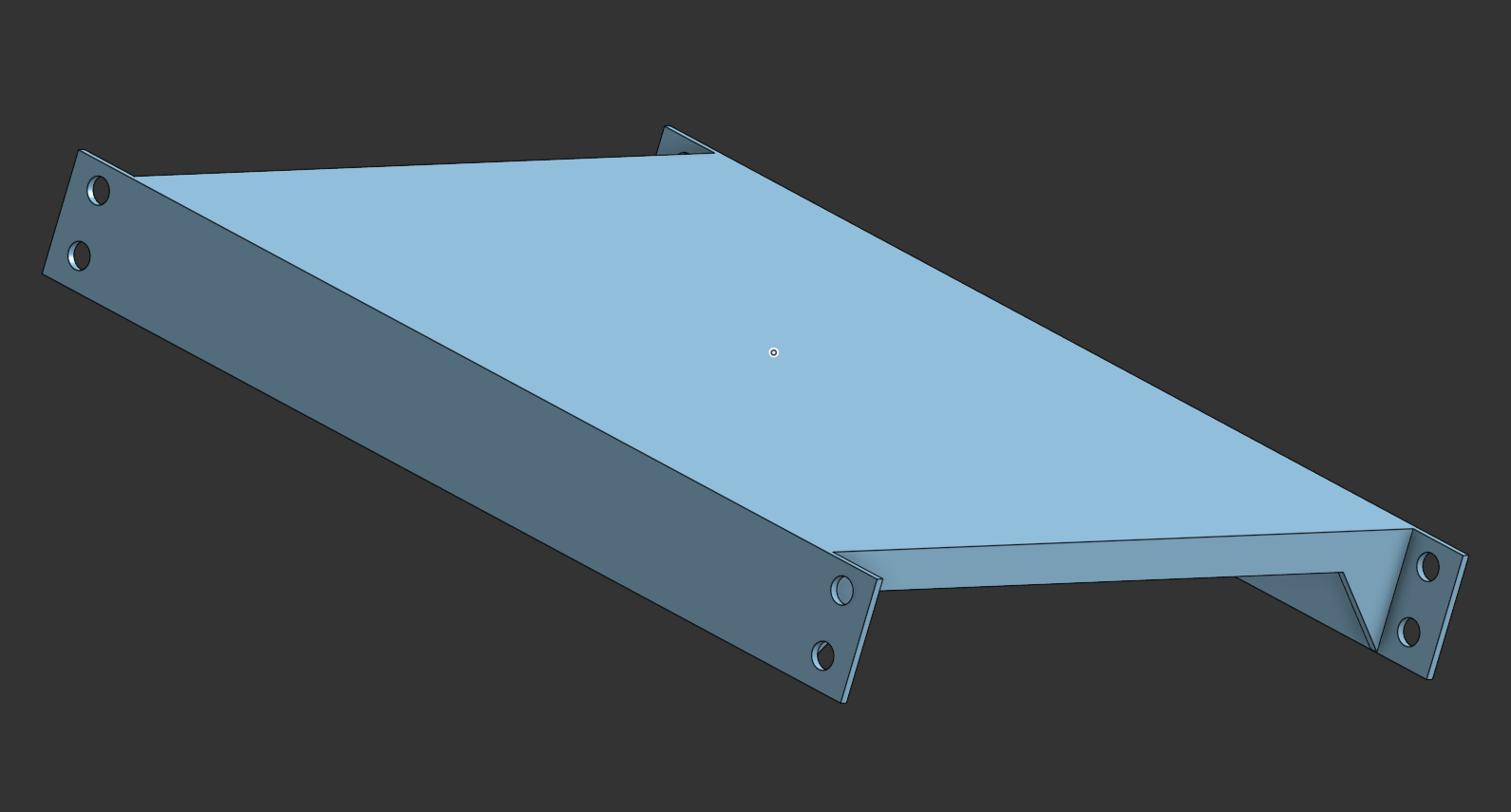
I instead decided to just create two 0.5U mounting plates and link the two together with a flat surface. This is definitely way less rigid than the previous plan, but it works well enough. Better get something out before the “less-than-perfect” sucks up all my motivation.
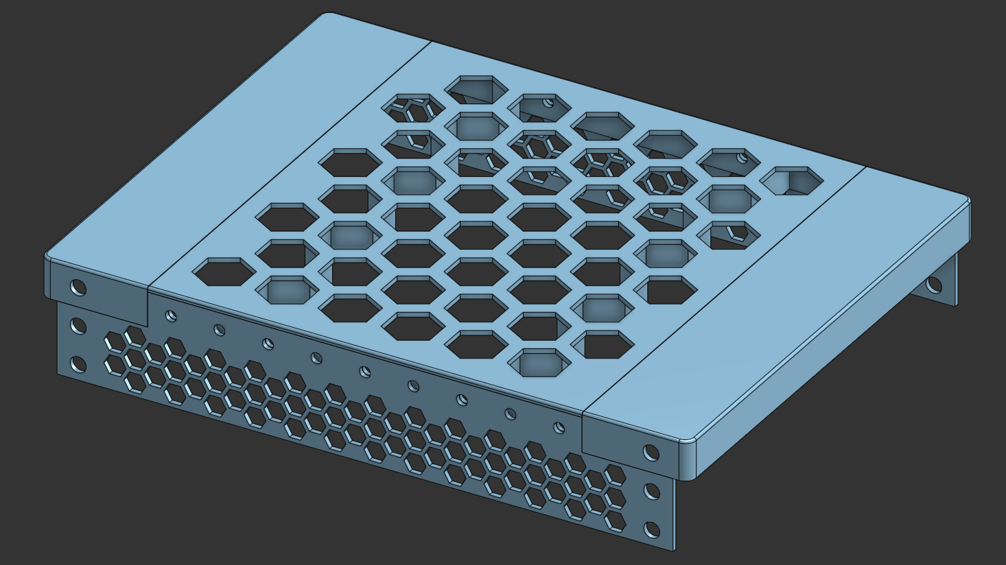
For the top of the rack, I broke it up into five different pieces since I wanted it to be more visually pleasing than the base which I’d rarely be seeing. The rails are mounted to two “edge” pieces which should hold each pair of rails in place. The front plates will hold the two pairs at the 10-inch width, while the top plate is just there to act as a surface to put things on.
In hindsight, I probably could have made things way simpler, but this is what I’ve printed, and I’m sticking with it.
The equipment mounts
I mounted my equipment to the rack in order of least to most important. The first thing I mounted my existing Huawei router. I was hoping that I could just slot it into the rack, but it was too wide. Since I couldn’t fit it in, I just put it on the top of the rack.
Next was the PoE switch that I got from TaoBao. It’s an 8-port 2.5GbE switch with PoE, and it’ll be the most important part of the rack when everything is set up. But for now it’s not in use at all, so it goes in first. Designing the mount for it was fairly simple. I just took a 1U front plate, added a tall hollow rectangle to hold the switch, and a separate back plate to hold the switch in place. I also cut a big hole in the side of the switch holder where the ventilation holes on the switch are. I had abit of leftover space, so I added a keystone-sized hole for the power cable to go through.
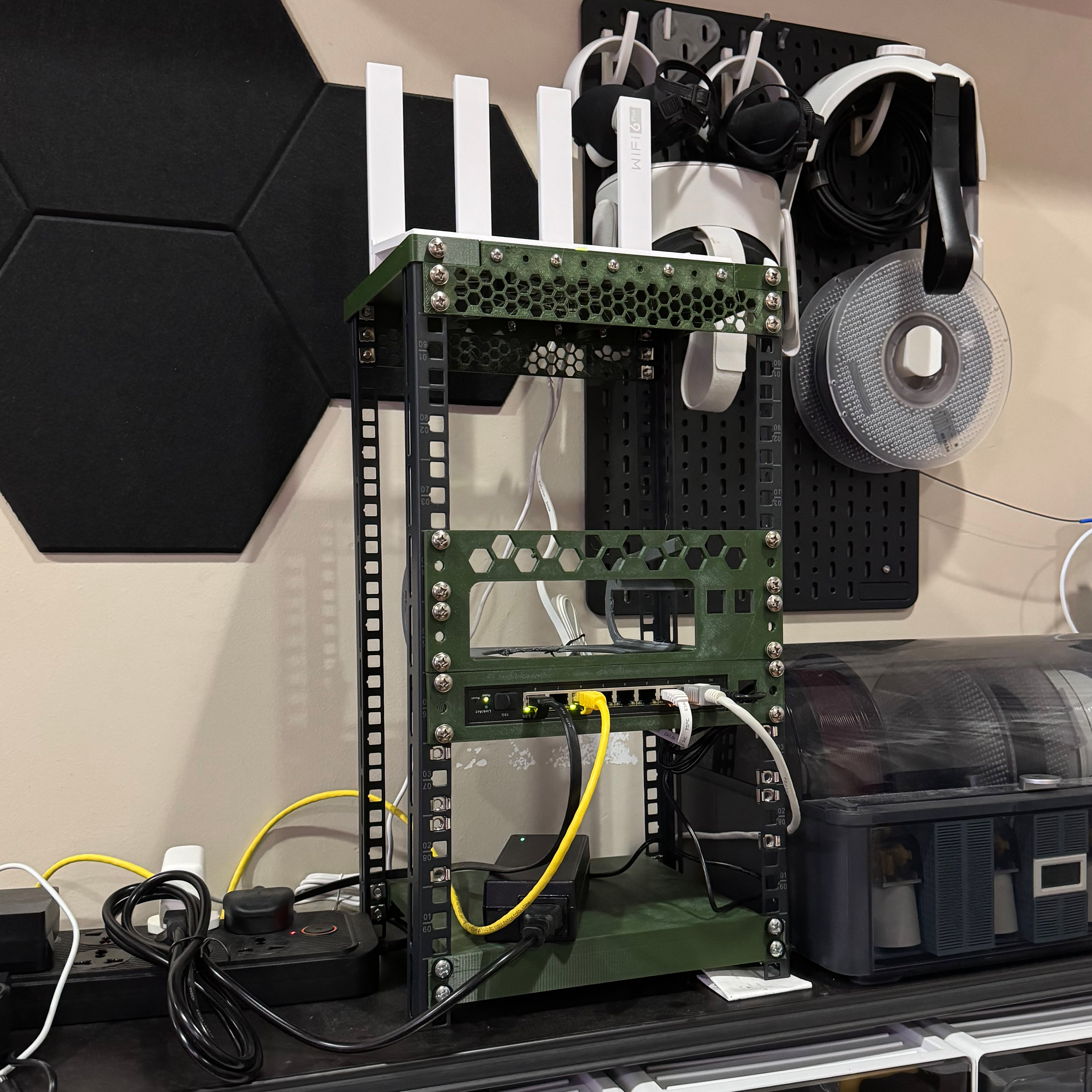
Next, I started working on the rack mount for the new N100 mini-pc (which I will now be referring to as the Brick). The Brick has a full metal enclosure that doubles as a heatsink for passive cooling. This means that I needed to allow as much ventilation as possible. The issue is that there are cooling fins on the top and both sides of the Brick, and a ventilation hole on the bottom, so I had to design the mount to allow airflow to all of those features.
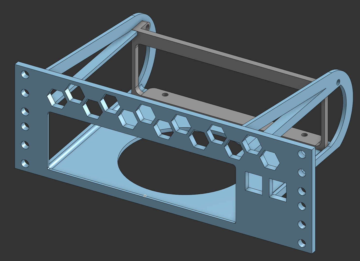
This part took the longest to design, but in the end I managed to create a mount that held the Brick by its four corners, and had a hole in the bottom for ventilation. I also added a hex pattern to the top of the mount since I had some leftover space. I’m not sure if it’ll actually help with cooling, but it looks cool. I also added two keystone-sized holes for the power cable and whatever else I might need to plug into the Brick.
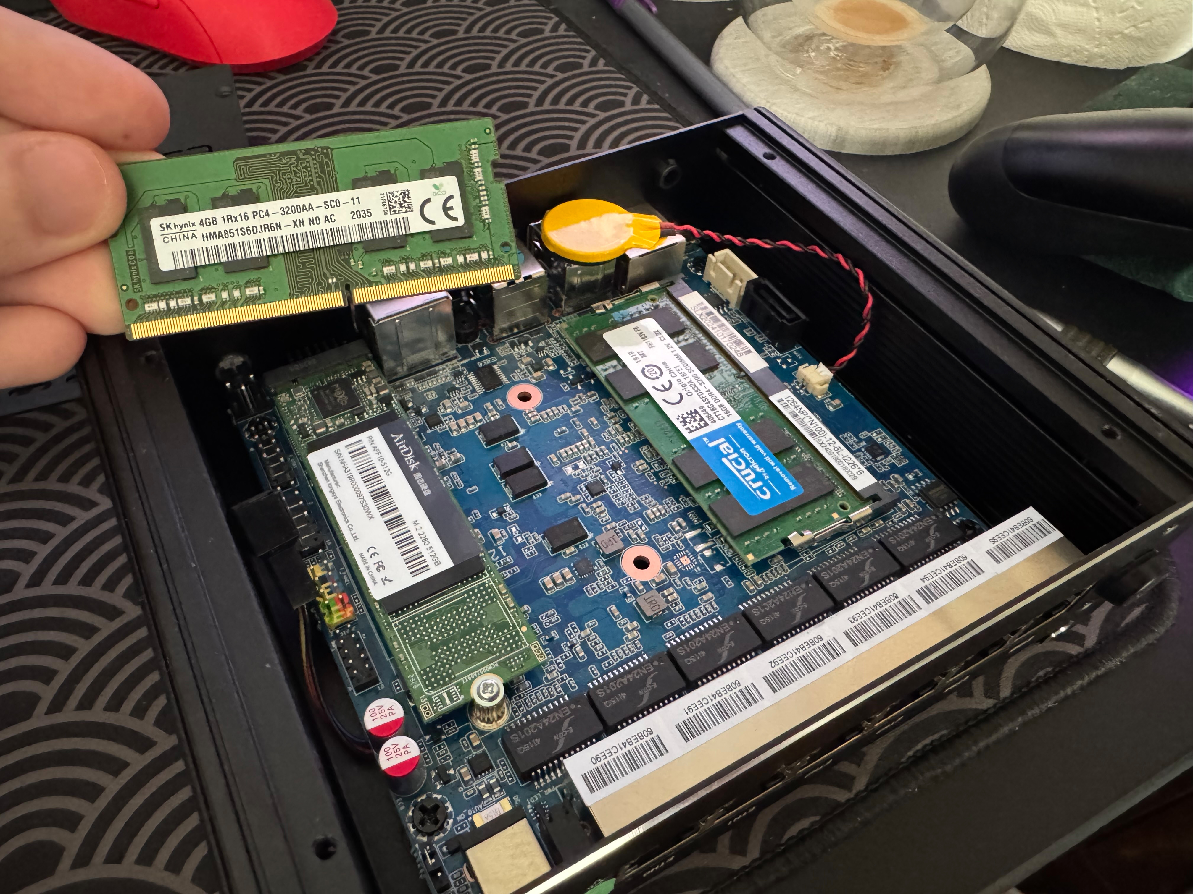
Before mounting the Brick, I did a quick upgrade to it. I replaced the 128GB SSD with a 512GB SSD that I had spare, and replace the 4GB of RAM with a 16GB SODIMM of RAM from Crucial. As a side-note, I’m surprised the Brick came with RAM from SK Hynix. I thought a TaoBao mini-pc would come with some no-name brand, but I guess I was wrong.
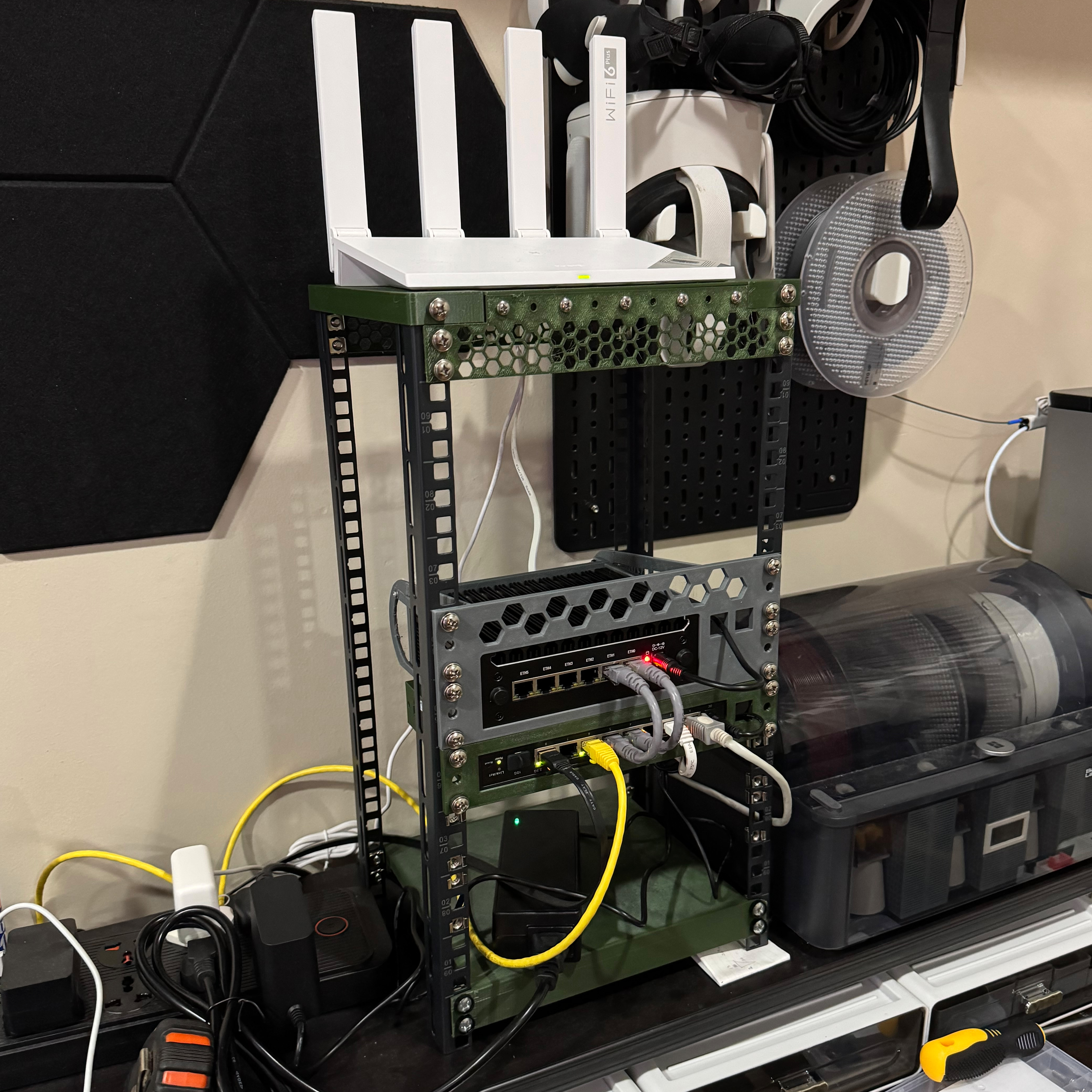
The last piece of equipment to mount was my existing Larkbox X mini-pc. This was similar the the brick, but without as much ventilation requirements. The Larkbox only has a single vent on the top, and a smaller one on the back, so I just left the top open. I also added a hex pattern to the top of the mount. The Larkbox is a fasir bit narrower than the Brick, so I had enough space on the side to mount a Raspberry Pi. I’m using a RasPi 3B+ that I salvaged from an old 3d printer that I’m not using anymore.
I also added a keystone-sized hole for the RasPi’s ethernet, and a hole to fit a 0.96” OLED display that I had lying around. I’ll likely be using the RasPi as a DNS server, so having a display for its IP address would be useful.
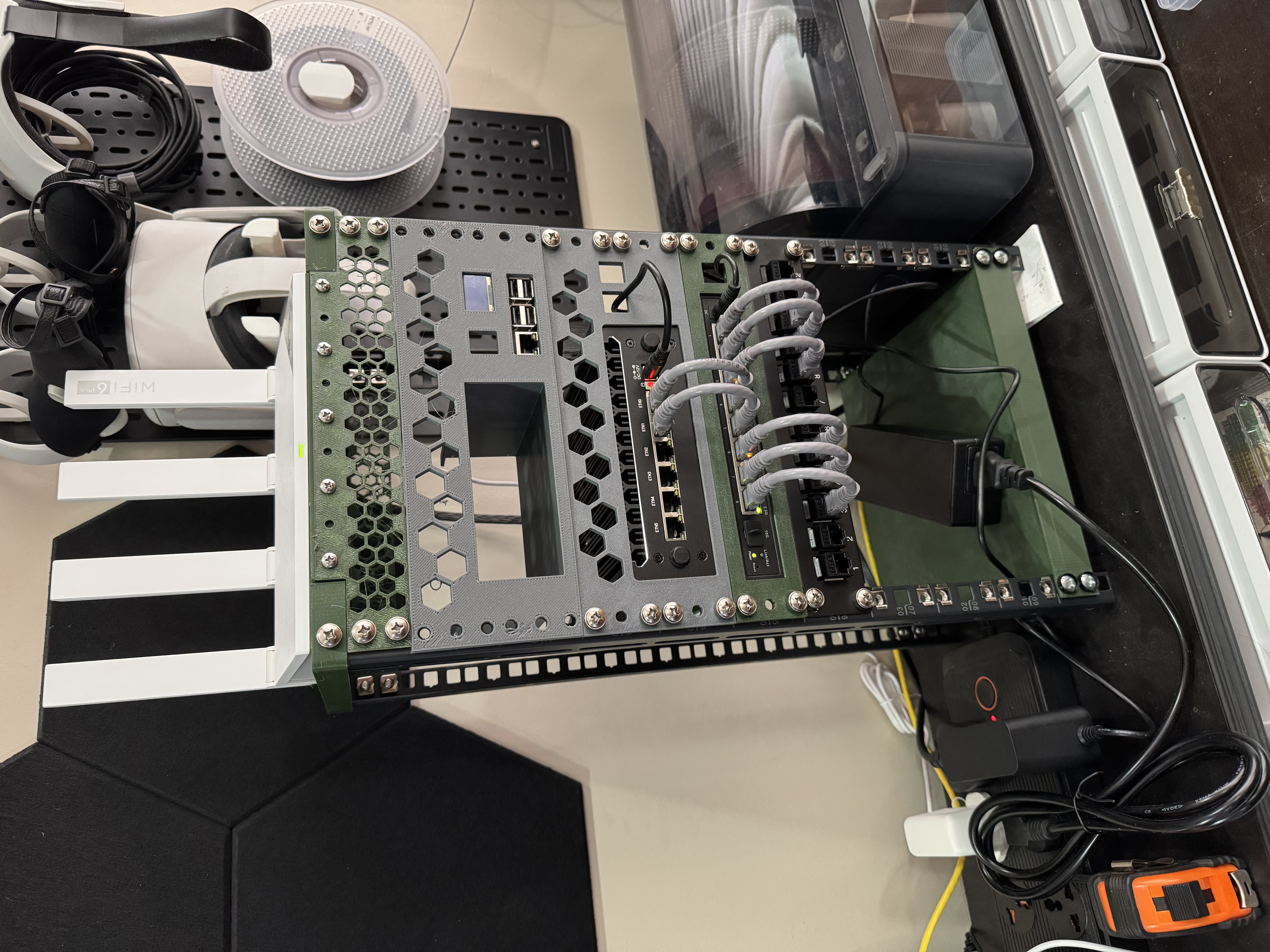
I also added a 1U keystone panel to the rack. This is mainly for cosmetic reasons, since it lets me route cables more neatly, and I get to use these super short 10cm patch cables that I got from TaoBao. It isn’t any better than just plugging the cables directly into the switch, but it looks nice and give me a real “cosplaying as a sysadmin” vibe.
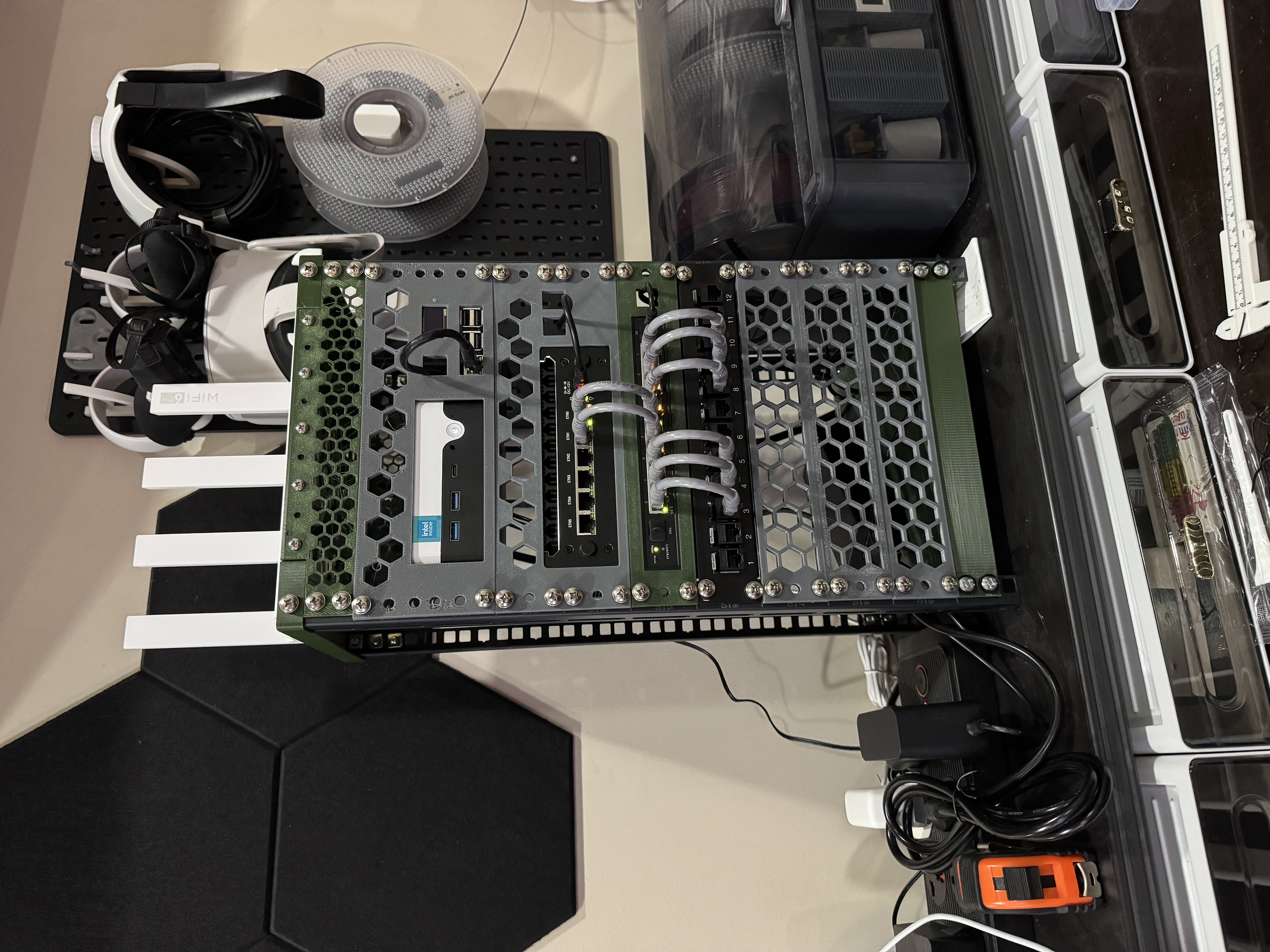
Finally, I added some vented panels to cover the empty 3U of space at the bottom. I’m not going to be filling this in anytime soon. For now it’s just going to be where my cables and power bricks go. I’ve also got a PDU on the way, so I’ll be able to power everything from a single power outlet.
Conclusion
With everything physically mounted to the rack, it’s time to get to the trickier part of things. Setting up the software side of things will be a bit more complicated, so I’ll cover that in a future post. For now, I’m just happy that I’ve gotten this far. I’ve been wanting to do this for a while now, and I’m glad that I finally got around to it.